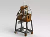
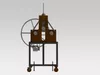
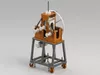
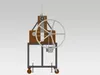
Tube & Profile Bending Machine – Professional Digital Machine Design
Build your own professional Tube & Profile Bending Machine with a complete engineering design package developed for fabrication, machining and workshop use.
This is a complete machine design package, not a simple sketch or basic DXF collection. It includes 3D CAD models, CNC/laser-cut DXF files, detailed technical drawings, assembly drawings, a complete 336-component part list and an Excel bending calculator.
MACHINE CONFIGURATION
The machine uses a three-roll bending arrangement consisting of:
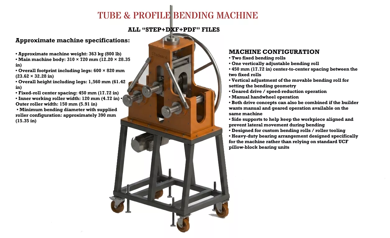
2 fixed bending rolls1 vertically adjustable bending roll450 mm (17.72 in) center-to-center spacing between the two fixed rollsVertical adjustment of the movable roll for controlling the bending geometryGeared drive / speed-reduction operationManual handwheel operationThe machine can be configured for geared operation only, manual operation only, or both methods togetherSide supports help keep the tube or profile aligned and prevent lateral movement during bendingReplaceable bending rolls mounted on dedicated bending roll shaftsHeavy-duty bearing arrangement designed specifically for this machine; standard UCF pillow-block bearing units were not usedBENDING ROLLS & WORKING WIDTH
The supplied bending-roll configuration provides approximately:
120 mm (4.72 in) working width on the inner side150 mm (5.91 in) working width on the outer side
The 150 mm bending width must not be confused with the 450 mm roller spacing. The 450 mm dimension refers only to the center-to-center distance between the two fixed bending rolls.
If a wider bending section is required, the builder can manufacture suitable custom bending rolls or external roller tooling to extend the usable bending-roll width beyond the standard 150 mm (5.91 in).
No fixed maximum extended width is claimed. The achievable width depends on the custom tooling, shaft arrangement, workpiece geometry and machine capacity.
Custom bending rolls can be designed for round tubes, pipes, square tubes, rectangular profiles and other suitable sections. The buyer can manufacture application-specific tooling and install it on the bending roll shafts using the designed mounting arrangement.
MINIMUM BENDING DIAMETER
The current bending-roll configuration is designed for a minimum bending diameter of approximately:
390 mm (15.35 in)
This value applies to the supplied roller configuration and should not be interpreted as an absolute limitation of the machine concept.
By manufacturing alternative bending rolls / custom tooling, smaller target bending diameters may be possible depending on the material, profile geometry, wall thickness, tooling geometry, springback, friction, available torque and overall machine capacity.
DRIVE OPTIONS – GEARED OR MANUAL
The machine was designed to provide flexible operating options.
GEARED DRIVE:The machine can be operated with a suitable gear reducer / speed reducer. This is suitable for powered and repeated bending operations.
MANUAL DRIVE:Builders who do not want to use a gearbox can operate the machine manually using the handwheel.
COMBINED CONFIGURATION:The machine can also be configured to retain both the manual handwheel and a suitable gear reducer, allowing the builder to choose the preferred operating method.
The gear reducer and motor are not included as physical components. The builder selects suitable drive components according to the intended application.
LOW-WELD / BOLTED CONSTRUCTION
The machine was designed with minimum welding requirements in mind.
Many components are joined using bolts and nuts, allowing the machine to be assembled, disassembled, serviced and modified more easily.
If the fabricator prefers a permanently welded structure, the design can also be adapted for welding.
Both approaches are supported:
Bolted / knock-down assembly for easier manufacturing, transport, service and modificationOptional welded assembly for a permanently rigid structure
This allows the final manufacturing method to be selected according to the builder's workshop equipment, capabilities and preferences.
HEAVY-DUTY BEARING DESIGN
The machine was not designed around ready-made UCF pillow-block bearing housings.
Instead, the bearing arrangement was developed around heavy-duty bearings and dedicated machine components suitable for the intended load path.
This provides a more integrated mechanical design and gives the builder greater control over the bearing, shaft and housing arrangement.
MACHINE SIZE & WEIGHT
Approximate machine specifications:
Machine weight: 363 kg (800 lb)Main machine body: 310 × 720 mm (12.20 × 28.35 in)Overall footprint including legs: 600 × 820 mm (23.62 × 32.28 in)Overall height including legs: 1,560 mm (61.42 in)Fixed-roll center spacing: 450 mm (17.72 in)Inner working roller width: 120 mm (4.72 in)Standard outer working roller width: 150 mm (5.91 in)Minimum bending diameter with supplied roller configuration: approximately 390 mm (15.35 in)
Dimensions are approximate. Always verify the supplied technical drawings before fabrication.
SIDE SUPPORTS / WORKPIECE GUIDANCE
The machine includes side supports designed to help keep the tube or profile correctly positioned during bending.
These supports reduce lateral movement and help the operator maintain controlled bending, particularly when working with longer sections or profiles.
COMPLETE DIGITAL ENGINEERING PACKAGEDXF.zip
Contains all DXF files for parts intended to be manufactured by CNC or laser cutting.
Excel.zip
Contains:
Tube & Profile Bending Machine Full Part List.xlsxComplete list of all 336 individual components, including quantities and part details.
Roller_Calculator_V8.xlsxExcel bending calculation tool to assist with planning and calculating the bending operation.
PDF01.zip
First part of the complete PDF technical documentation.
PDF02.zip
Second part of the complete PDF technical documentation.
The PDF documentation is divided into two ZIP files because the complete PDF package exceeds the available individual file-size limit.
Step.zip
Contains:
PRB02-000-000 (AP-214).STEP – STEP AP214 version
PRB02-000-000 (AP-203).STEP – STEP AP203 version
Both STEP standards are included to improve compatibility with different CAD systems.
TECHNICAL DRAWINGS & ASSEMBLY DOCUMENTATION
The PDF documentation contains detailed technical drawings for the machine parts and detailed assembly drawings.
The drawings provide manufacturing dimensions and technical information required to reproduce the designed components.
Assembly drawings show the relationship and installation of the components within the complete machine.
The package is intended as a complete engineering reference for manufacturing and assembly, not merely a conceptual drawing set.
336 COMPONENTS – 87 UNIQUE PART DESIGNS
The complete machine assembly consists of approximately:
87 unique part designs / part types336 total individual components
The Excel part list provides the quantities and details for the complete assembly.
BENDING CALCULATION FILE INCLUDED
Roller_Calculator_V8.xlsx is included as an engineering aid for bending calculations and roller-position planning.
Actual bending results may vary according to material properties, section geometry, wall thickness, springback, friction, tooling geometry and operating conditions.
WHO IS THIS DESIGN FOR?
Suitable for:
Metal fabrication workshopsTube and profile fabricatorsMechanical engineersMachine buildersMachinistsWelding and fabrication shopsCNC / laser-cutting workshopsCustom machinery manufacturersAdvanced DIY machine buildersEngineering and technical education projects
The builder should have suitable fabrication and machining capabilities, or access to an appropriate workshop.
IMPORTANT – DIGITAL PRODUCT ONLY
THIS LISTING IS FOR A DIGITAL PRODUCT ONLY.
NO PHYSICAL MACHINE WILL BE SHIPPED.
No finished machine, metal parts, bending rolls, shafts, bearings, gearbox, motor, fasteners or other physical components are included.
You are purchasing the digital engineering files and documentation used to manufacture the machine.
The buyer is responsible for selecting suitable materials, manufacturing methods, bearings, shafts, drive components, gearbox/motor specifications, fasteners, guards and other components according to the intended application.
The final machine must be properly manufactured, assembled, guarded, tested and operated by a competent person and in accordance with applicable machinery safety requirements and local regulations.