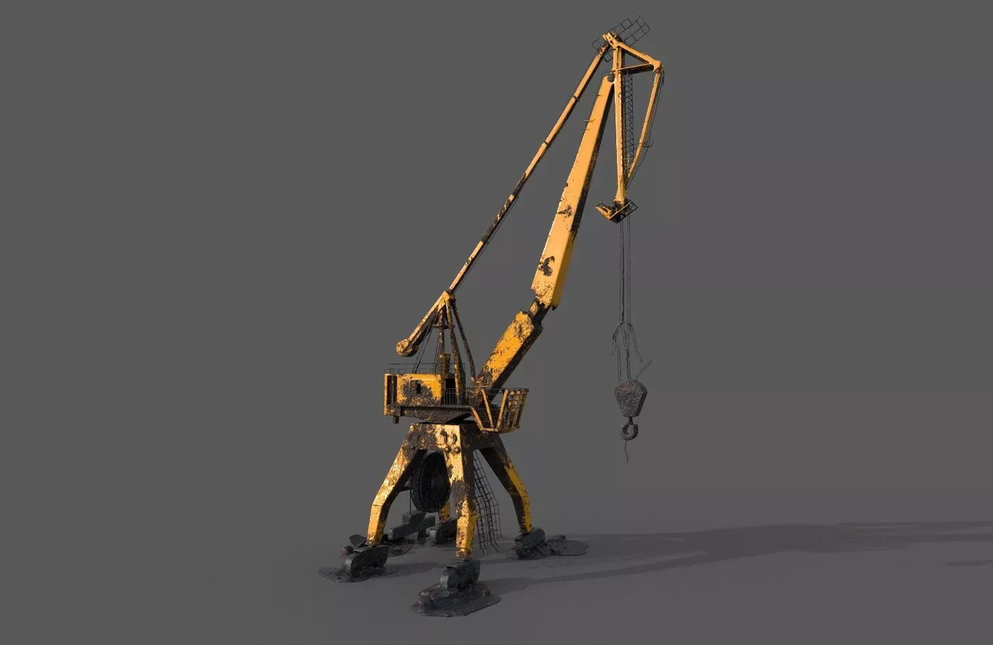
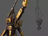
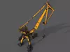
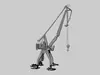
A crane is a machine used to move materials both vertically and horizontally, utilizing a system of a boom, hoist, wire ropes or chains, and sheaves for lifting and relocating heavy objects within the swing of its boom. The device uses one or more simple machines, such as the lever and pulley, to create mechanical advantage to do its work.[1] Cranes are commonly employed in transportation for the loading and unloading of freight, in construction for the movement of materials, and in manufacturing for the assembling of heavy equipment.
The first known crane machine was the shaduf, a water-lifting device that was invented in ancient Mesopotamia (modern Iraq) and then appeared in ancient Egyptian technology. Construction cranes later appeared in ancient Greece, where they were powered by men or animals (such as donkeys), and used for the construction of buildings. Larger cranes were later developed in the Roman Empire, employing the use of human treadwheels, permitting the lifting of heavier weights. In the High Middle Ages, harbour cranes were introduced to load and unload ships and assist with their construction—some were built into stone towers for extra strength and stability. The earliest cranes were constructed from wood, but cast iron, iron and steel took over with the coming of the Industrial Revolution.
For many centuries, power was supplied by the physical exertion of men or animals, although hoists in watermills and windmills could be driven by the harnessed natural power. The first mechanical power was provided by steam engines, the earliest steam crane being introduced in the 18th or 19th century, with many remaining in use well into the late 20th century.[2][3] Modern cranes usually use internal combustion engines or electric motors and hydraulic systems to provide a much greater lifting capability than was previously possible, although manual cranes are still utilized where the provision of power would be uneconomic.
There are many different types of cranes, each tailored to a specific use.[4] Sizes range from the smallest jib cranes, used inside workshops, to the tallest tower cranes, used for constructing high buildings. Mini-cranes are also used for constructing high buildings, to facilitate constructions by reaching tight spaces. Large floating cranes are generally used to build oil rigs and salvage sunken ships.[citation needed]
Some lifting machines do not strictly fit the above definition of a crane, but are generally known as cranes, such as stacker cranes and loader cranes.
EtymologyCranes were so called from the resemblance to the long neck of the bird, cf. Ancient Greek: γερανός, French grue.[5]
HistoryAncient civilizationsThe earliest known lifting device was the shadoof, a crane-like device used in Mesopotamia around 3000 BCE, which had a lever mechanism and was used for irrigation purposes.[6][7][8][9] It was invented in Mesopotamia (modern Iraq) circa 3000 BC.[7][8] The shadouf subsequently appeared in ancient Egyptian technology circa 2000 BC.[9][10] However, the transition to building cranes occurred in ancient Greece during the late 6th century BCE.[11] Archaeological evidence, including distinctive cuttings for lifting tongs and Lewis irons on stone blocks of Greek temples, indicates a fundamental shift in engineering strategy coinciding with the development of the Greek city-state (polis).[12] Since these holes point at the use of a lifting device, and since they are to be found either above the center of gravity of the block, or in pairs equidistant from a point over the center of gravity, they are regarded by archaeologists as the positive evidence required for the existence of the crane.[11]
This labor constraint necessitated mechanical advantage provided by the winch and pulley system, replacing labor-intensive ramps. In contrast to the archaic period with its pattern of ever-increasing block sizes, Greek temples of the classical age like the Parthenon invariably featured stone blocks weighing less than 15–20 metric tons. Also, the practice of erecting large monolithic columns was practically abandoned in favour of using several column drums.[13]
Although the exact circumstances of the shift from the ramp to the crane technology remain unclear, it has been argued that the volatile social and political conditions of Greece were more suitable to the employment of small, professional construction teams than of large bodies of unskilled labour, making the crane preferable to the Greek polis over the more labour-intensive ramp which had been the norm in the autocratic societies of Egypt or Assyria.[13]
The first unequivocal literary evidence for the existence of the compound pulley system appears in the Mechanical Problems (Mech. 18, 853a32–853b13) attributed to Aristotle (384–322 BC), but perhaps composed at a slightly later date. Around the same time, block sizes at Greek temples began to match their archaic predecessors again, indicating that the more sophisticated compound pulley must have found its way to Greek construction sites by then.[14]
Roman EmpireSee also: Treadwheel crane
Greco-Roman Trispastos (Three-pulley-crane), a simple crane type (1800 N load)
Greco-Roman Pentaspastos (Five-pulley-crane), a medium-sized variant (c. 6000 N load)
Reconstruction of a 10.4 m high Roman Polyspastos powered by a treadwheel at Bonn, GermanyThe heyday of the crane in ancient times came during the Roman Empire, when construction activity soared and buildings reached enormous dimensions. The Romans adopted the Greek crane and developed it further. There is much available information about their lifting techniques, thanks to rather lengthy accounts by the engineers Vitruvius[15] and Heron of Alexandria[16]. There are also two surviving reliefs of Roman treadwheel cranes, with the Haterii tombstone from the late first century AD being particularly detailed.
Roman relief from the Tomb of the Haterii showing a construction crane with a pulley systemRoman engineers advanced Greek designs by analyzing mechanical advantage ratios. The simplest Roman crane, the trispastos, consisted of a double-beam jib, a winch, a rope, and a block containing three pulleys. Having thus a mechanical advantage of 3:1, it has been calculated that a single man working the winch could raise 150 kg (330 lb) (3 pulleys x 50 kg or 110 lb = 150), assuming that 50 kg (110 lb) represent the maximum effort a man can exert over a longer time period. Heavier crane types featured five pulleys (pentaspastos) or, in case of the largest one, a set of three by five pulleys (Polyspastos) and came with two, three or four masts, depending on the maximum load[17].
The polyspastos represented a major leap in mechanical efficiency. When worked by four men at both sides of the winch, it could readily lift 3,000 kg (6,600 lb) (3 ropes x 5 pulleys x 4 men x 50 kg or 110 lb = 3,000 kg or 6,600 lb). If the winch was replaced by a treadwheel, the maximum load could be doubled to 6,000 kg (13,000 lb) at only half the crew, since the treadwheel possesses a much bigger mechanical advantage due to its larger diameter. This meant that, in comparison to the construction of the ancient Egyptian pyramids, where about 50 men were needed to move a 2.5 ton[which?] stone block up the ramp (50 kg (110 lb) per person), the lifting capability of the Roman polyspastos proved to be 60 times higher (3,000 kg or 6,600 lb per person).[18] However, substituting the winch with a treadwheel—a large wooden wheel rotated by men walking inside it—doubled this capacity to 6,000 kg with half the crew. This efficiency increase resulted from the treadwheel's larger diameter creating a much greater moment arm compared to a hand winch. This system increased lifting efficiency by 60 times compared to Egyptian pyramid construction, where approximately 50 men were required to move a 2.5-tonne stone block up a ramp.[19]