1/4
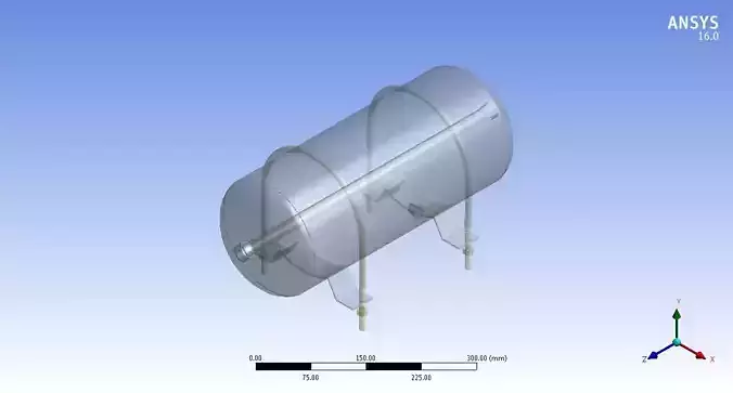
Model Overview: The air brake tank CAD model in SolidWorks is meticulously designed to adhere to industry standards, ensuring optimal functionality and integration within pneumatic brake systems.
Design Features: It incorporates a cylindrical tank body with precision-engineered end caps, designed for efficient air compression and storage. The inlet and outlet ports are strategically positioned to facilitate seamless air flow regulation.
Material Specifications: Crafted from high-grade stainless steel/aluminum alloy to withstand high-pressure environments, ensuring durability and safety in operational conditions.
Internal Structure: The interior includes baffles and partitions to prevent sloshing and ensure uniform air pressure distribution, enhancing stability and performance during braking maneuvers.
Mounting and Integration: The model features mounting brackets with standardized hole patterns, facilitating straightforward installation and compatibility with various vehicle chassis configurations.
CAD Detailing: Each component, from weld seams to bolt connections, is meticulously detailed in the CAD model, ensuring precise manufacturing guidelines and assembly procedures.
Simulation and Testing: Prior to production, the CAD model undergoes rigorous simulation tests within SolidWorks to validate structural integrity, pressure tolerance, and performance under varying operational conditions.
Compliance and Standards: Designed in accordance with DOT (Department of Transportation) regulations or equivalent standards, ensuring regulatory compliance and reliability in commercial vehicle applications.
Assembly Documentation: Detailed assembly drawings and exploded views accompany the CAD model, providing comprehensive guidance for assembly line technicians and maintenance personnel.
Future Development: Continuous improvement and feedback integration ensure that the CAD model evolves to meet emerging industry requirements and technological advancements in pneumatic braking systems.
REVIEWS & COMMENTS
accuracy, and usability.


