Summary
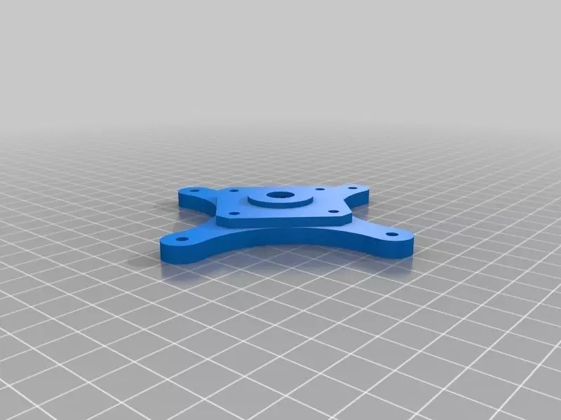
This is a 4.36:1 planetary gearbox intended to be inserted between your NEMA 17 extruder motor and your extruder mechanism. This allows you to use your existing Airtripper or similar extruder and your MK7 drive gear with a 5mm bore, yet still insert a gear reduction so your motor doesn't overheat.
This design is based on my custom gearhead extruder, but I have extracted just the gear reduction mechanism and given it a face mounting plate which should allow you to mount it to your existing extruder. I have also redesigned it to use common metric bearings and bolts in place of the eclectic mix of parts out of my junk bin that the original design used.
Note - I have not yet actually assembled and tested this design, these files are unproven. The design it's based on has been running smoothly for hours, but I haven't tested these modifications yet.
This design is unproven, use at your own risk. Feedback is welcome if you do print and build it.
Instructions
You will need the following hardware:
8x 625 bearings
3x 25mm long M5 screw
1x 40mm long M5 hex head bolt
4 M5 hex nuts
4x 50mm long M3 screws
8x 20mm long M3 screws
4x 10mm long M3 screws
3x M3 set screws
15x M3 hex nuts
Your existing motor and extruder
You will need to print three of the 'Planet' part, and one of each of all the other parts.
To assemble:
Remove your motor from your extruder. Save the mounting hardware.
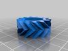
Insert two 625 bearings into each Planet gear, one in each side.
Push the 40mm M5 bolt into the Carrier piece from the underside. The hex head of the bolt should fit snugly into the cavity in the underside of the carrier. Thread a M5 hex nut onto the bolt from the other side and turn it until it's tight against the plastic. This will hold the bolt in place to the carrier. After installing the M5 bolt, press one 625 bearing into the cavity in the underside of the carrier.
Push one M5 hex nut into each of the three hexagonal pockets in the underside of the Carrier part. Thread a 25mm M5 screw in through the top of the Carrier and through the nut. Tighten well, you don't want these coming loose.
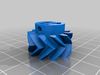
Push three M3 hex nuts into the three cavities on the Sun gear. Make sure the holes on the hex nuts are lined up with the holes in the plastic. Now turn three M3 set screws into the holes and thread them into the nuts. Push the Sun gear onto the output shaft of your motor, with the end of the sun gear with the set screws closer to the motor face. Don't tighten the screws yet, you'll want to wait until assembling the gearbox to tighten that down.
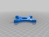
Attach the 'Rear Plate' part to your motor with four 10mm M3 screws. The side of the plate that's against the print bed goes against the motor face.
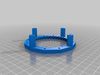
Put the 'Ring Back' piece against the 'Rear Plate' part. The flatter side of the ring should face away from the motor. Now insert the three planet gears between the ring and the sun gear. Note that the orientation of the planet gears matters, they only go in one way. You will want to get them evenly spaced 120 degrees around the sun gear. The 'carrier' piece can be used for this, as it will lock the three planets in place. You can also tighten the three set screws on the Sun gear at this point.
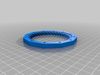
Once you have the planets and the carrier in place, you can install the 'Ring front' part. This only goes on one way, there are alignment arrows on the two halves of the ring gear that should line up. Use the 8 20mm long M3 screws through the 8 holes in the ring gear halves to screw them together tightly, you don't want them to be able to move relative to each other.
Put four M3 hex nuts into the four small hex cavities in the 'Front Plate' piece, these are for mounting it to your extruder. Push one 625 bearing into the circular cavity in the underside of the 'Front Plate' piece. Now slide the front plate over the M5 bolt, and line up the 4 mounting holes on the plates and the 4 long posts on the ring gear assembly. Use the 50mm long M3 screws thru the mounting holes to clamp everything together. Tweak the alignment until you can push the carrier around by hand. You may need to run the motor for an hour or so until the gearbox works smoothy.
You should be able to use the gear assembly in place of your existing motor, attaching it to your extruder by the 4 M3 hex nuts on the front, and attaching your drive gear to the M5 bolt. The M5 bolt isn't as well supported as a motor output shaft would be, so you'll want to make sure your extruder has a second 625 bearing on the output shaft to help support it.
ETA: I have added the source files for this project. Only the gears are scad, the rest of the parts are hand-drawn in Autocad. The Autocad files are also all scaled in inches, so you'll need to rescale them before exporting to metric stl files.