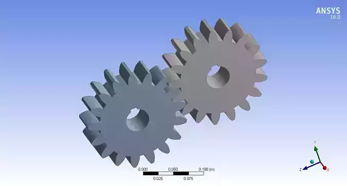
Designing spur gears involves several considerations to ensure proper functionality and durability in various mechanical systems. Spur gears are one of the simplest and most common types of gears, characterized by straight teeth that are parallel to the axis of rotation. Here are the key aspects involved in spur gear design:
- Gear SpecificationsPitch Circle Diameter (PCD): The theoretical circle on which the pitch circle lies. It determines the size of the gear.Module (Metric) or Diametral Pitch (Imperial): Defines the size of the teeth and pitch circle. Module is the distance between corresponding points on adjacent teeth in millimeters, while Diametral Pitch is the number of teeth per inch of pitch diameter.Pressure Angle: The angle between the line of action (the line along which the force is transmitted) and the line tangent to the pitch circle. Common pressure angles are 14.5°, 20°, and 25°.Number of Teeth: Determines the gear ratio and affects the size and strength of the gear.
- Materials and Heat TreatmentMaterial Selection: Gears are commonly made from alloy steels, such as 4140 or 8620, for their strength and durability. For specialized applications, materials like brass or nylon might be used.Heat Treatment: Harden gears to increase their strength and wear resistance. This process can involve quenching and tempering or carburizing and quenching.
- Design CalculationsPitch Diameter: Calculated from the number of teeth and the module or diametral pitch.Addendum and Dedendum: Addendum is the height of the tooth above the pitch circle, while dedendum is the depth of the tooth below the pitch circle.Clearance: The space between the teeth of mating gears to ensure smooth engagement and avoid interference.
- Strength and Durability ConsiderationsTooth Strength: Calculate bending stress and contact stress to ensure the teeth can withstand the forces and torque applied.Surface Durability: Ensure the gear teeth are hard enough to resist wear and withstand repeated contact stress.Fatigue Resistance: Design for sufficient fatigue life based on the anticipated load cycles.
- Manufacturability and TolerancesTooth Profile: Use standard tooth profiles such as involute, which ensures smooth and efficient power transmission.Machining Tolerances: Consider tolerances for gear tooth dimensions, surface finish, and alignment to ensure proper meshing and minimal noise.
- Assembly and TestingGear Meshing: Verify proper meshing of gears to minimize backlash (play between gears) and ensure smooth operation.Testing: Conduct tests to verify gear strength, noise level, and efficiency under operating conditions.
- LubricationGear Lubrication: Ensure proper lubrication to reduce wear and friction between gear teeth. Select lubricants suitable for the operating conditions (temperature, load, speed).Software Tools:CAD Software: Use software like SolidWorks, AutoCAD, or similar to design and visualize gears.Gear Design Software: Specialized software such as KISSsoft or Gearotic Motion can aid in gear design, analysis, and simulation.In summary, spur gear design involves careful consideration of dimensions, materials, strength calculations, and manufacturing processes to ensure reliable and efficient operation in various mechanical systems. Advanced design tools and calculations are essential to optimize performance and durability while meeting specific application requirements.


