Summary
After running my Rostock printer for a while, I've determined that the extruder motor really needs a geared reduction. It's not that the motor doesn't have enough torque, but that producing the required torque causes the motor to run hot, which can affect the ability to grip the filament or even deform the motor mount. It also causes the motor driver board to overheat and cut out. I'm only running a 0.5mm nozzle, but these problems only get worse with a 0.35mm nozzle.
Some people have switched to a stepper motor with an integrated planetary reduction. That works, but the gearbox on that has a shaft which is larger than the 5mm hole in the MK7 drive gear I'm using. I don't have access to the required machine tools to safely modify my drive gear for a larger shaft. So instead I decided to make my own gear reducer using stuff from my junkbox.
The gear assembly itself is based on gear code from Emmett's Automatic Transmission Model: http://www.thingiverse.com/thing:34778
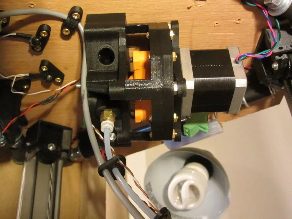
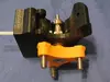
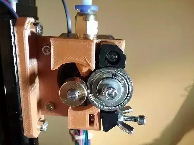
The extruder is originally based on the Airtripper extruder, but has been changed to the point of unrecognizability. I changed the design to use bearings and bolts I had on hand, and modified the pinch arm to use a single bolt with a hand-friendly knob to make it easy to adjust the pressure on the bearing.
I have also changed the design to use the following push-fit connector:
http://www.amazon.com/gp/product/B004M8T2QE/ref=oh_details_o00_s01_i00
This holds better than the all-plastic designs I had been using, and also makes it easy to remove the Bowden tube when required.
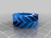
All of the gears have prime numbers of teeth, which in theory should cause them to wear more evenly over time. The final gear reduction is about 4.36:1.
I'm posting this design as a point of reference for anyone who is designing their own extruder using a printed gearbox. I don't recommend just printing these parts as-is as this design was specifically based around the bearings and bolts I had on hand. It's also fairly experimental as I don't know how printed gears will hold up long-term. I've run it for a few hours and it seems to be working so far.
Update: After running for about a year, the gearbox still works smoothly. Some wear on the gear teeth, but not enough to be a problem.
Video of the machine running at http://www.youtube.com/watch?v=4j0u2avXHYs
Instructions
I don't recommend anyone build this as-is. This design was specifically designed around bearings and bolts I had on hand, and is posted only as a reference for people coming up with their own design. The following instructions are what you would hypothetically have to do to reproduce this exact design:
You will need three of the planetgear part, and one of each of the other parts.
You will also need:
6X R4RS bearings
1X 1614RS bearing
3X 625 bearings
4X 1/4diameter, 1 1/4 long shoulder screws
4X hex nuts for the ends of the shoulder screws
1X 50mm M5 bolt
1X M5 hex nut
1X 50mm M4 bolt
1X M4 nut
2X washers to fit M4 bolt
1X spring to fit on M4 bolt, about 3/8long
1X SMC KQ2H04-01AS push-fit connector
4X 6-32 flat head screws, at least 2 long
4X 6-32 hex nuts
8X 4-40 screws, at least 1long
3X 4-40 screws, 1/4 long
9X 4-40 hex nuts
NEMA 17 motor
4x M3 screws to mount the motor
MK7 drive gear
The Motorplate part gets attached to the front of the motor with four M3 screws. Use low-profile screws if possible so the planet gears don't crash into them.
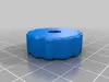
Three of the 4-40 hex nuts get pressed into the cavities in the sun gear, and then the three short 4-40 screws are threaded into them to secure the sun gear onto the motor shaft.
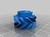
Each planetgear part gets two of the R4RS bearings pressed into it, one from each side.
The M5 bolt gets pressed into the carrier piece, from the bottom side, so that the hex head of the bolt is snug in the hex cavity in the carrier. One of the 625 bearings is then pressed into the carrier, covering the bolt head.
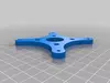
Press three of the hex nuts for the 1/4shoulder screws into the three hex cavities on the upper side of the carrier. Screw three shoulder screws in from the bottom side. Tighten them well, use locktite to make sure they're not going anywhere. Then get a Dremel tool or something similar and cut the heads of the bolts off, so they only extend half an inch from the carrier. These three bolts will carry the three planet gears, but you have to cut their heads off so they don't hit the motor. Don't worry, the fact that this is a herringbone gear assembly keeps them from going anywhere.
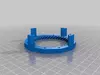
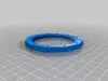
The partsringgearandringgear backhalfare the two halves of the outer ring gear. This part has to be made in two pieces because the gearbox would be very difficult to assemble otherwise. The two halves of the ring gear are held together with eight 4-40 screws, but the assembly can be a little tricky. The two ring halves only line up properly one way, so you have to look carefully at the teeth to make sure they line up properly when you're assembling them. In retrospect, I should have designed alignment marks into the pieces.
Theringgear backhalfpart goes closer to the motor, separated from theMotorplatepart by a gap defined by a single 6-32 hex nut. The three planet gears go equally spaced around the sun. The bearing in the center of the carrier piece fits over the end of the motor shaft, and the three cut-off bolts on the carrier locate the three planet gears. You can then fit theringgearpart over the carrier, being careful to line it up properly, and then anchor the two halves of the ring gear together with eight 4-40 screws. Once you're sure you have the orientation right, those screws should be really tight with locktite on the nuts - you don't want these loosening up over time.
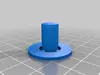
TheAxlepart has a flange which is just there to help it print more reliably. Cut that bit off after printing it. The Axle then goes through the 1614RS bearing, which is then pressed into theArmpiece.
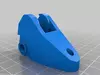
TheBodypiece has a bit of support material in the pocket where the arm mounts. Cut the support material away, and then secure the arm in place with the last 1/4 shoulder screw.
Drill out the filament path thru passage on the body with a 4mm drill. Cut two pieces of bowden tube - one about .3long, one at least 1.5 long - to fit into the passage. This will guide the filament through the extruder block.
Use a socket head driver to screw the push-fit connector into the bottom of the Body part. There are no printed screws threads, but they aren't really needed as the brass threads on the push-fit connector will cut into the plastic. Make sure you thread the connector in straight, having it at any angle will make it harder to feed filament through.
Press two 625 bearings into the Body, one from the rear and one from the front. Place the MK7 drive gear between the bearings, and then lower the body assembly over the M5 bolt that is the output shaft from the gear reducer. Use four 6-32 flathead screws to secure the motor, gear reducer, and extruder body together. Turn a M5 hex nut over the exposed end of the M5 screw, and then tighten the set screw on the MK7 drive gear to secure it to the M5 bolt.
Press the M4 screw through the Knob part, so that the hex head on the screw is firm in the hex pocket on the knob. Put a washer, a spring, and then another washer over the screw. Feed the screw through the hole in the arm, and the hole in the flange on the body. The M4 hex nut goes in the pocket on the flange, and the M4 screw threads into it.
The extruder mounts to the underside of the top structural plate on the printer by three M3 screws. If you're mounting the extruder somewhere other than the top inside center of your printer, you'll have to figure a different mounting scheme.
That's about it. I've only run mine for a few hours so far, but it seems to run smoothly. The motor is getting mildly warm at most, and the stepper motor driver has yet to overheat. It seems to be performing very well, retraction during move especially is quite crisp and there's not much ooze. I'm going to have to run it for a while to know the long-term reliability of the printed gears.
ETA: I have added the source files for this project. Only the gears are scad, the rest of the parts are hand-drawn in Autocad. The Autocad files are also all scaled in inches, so you'll need to rescale them before exporting to metric stl files.