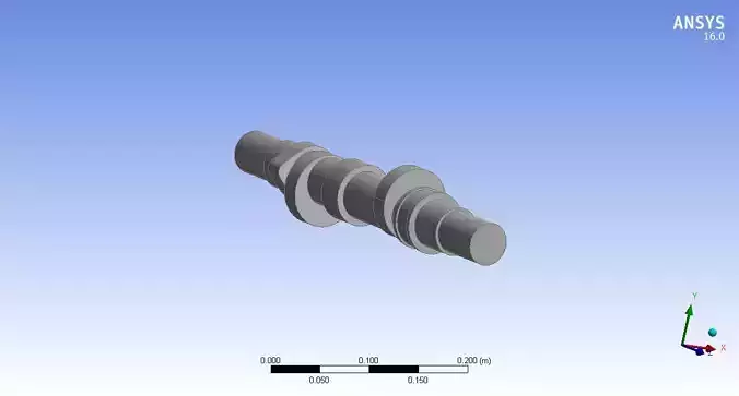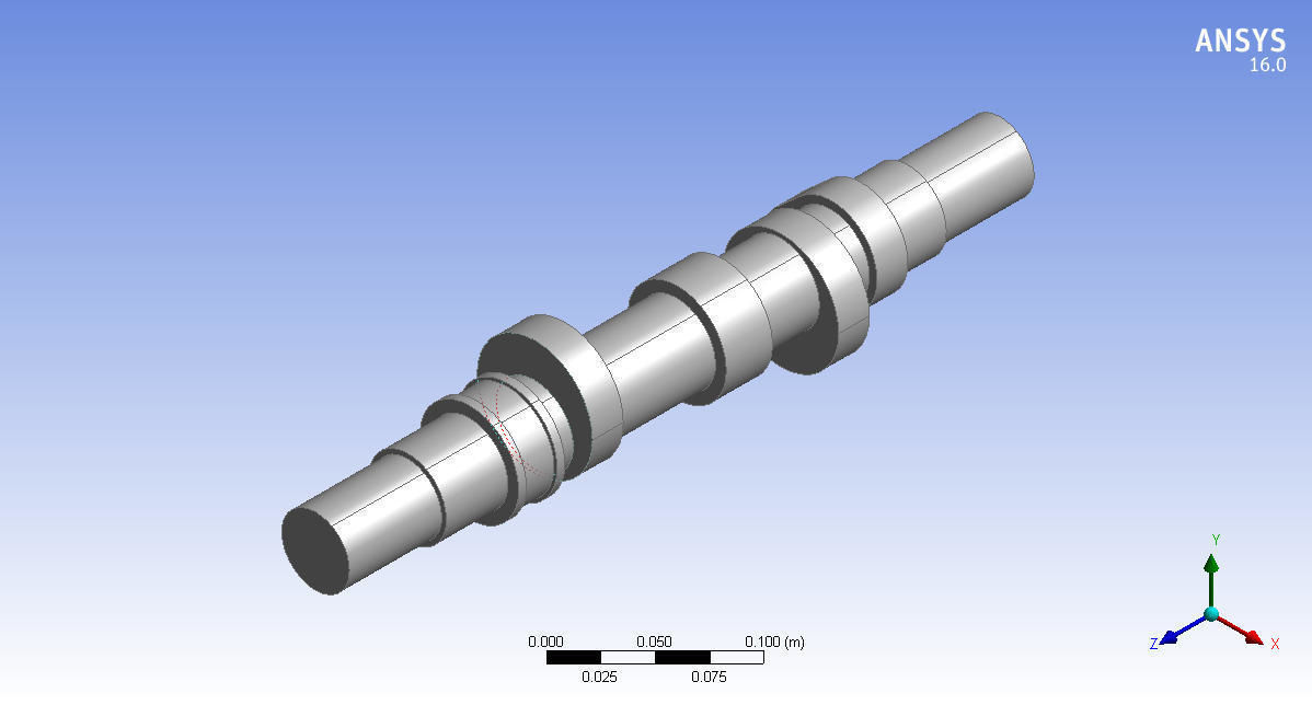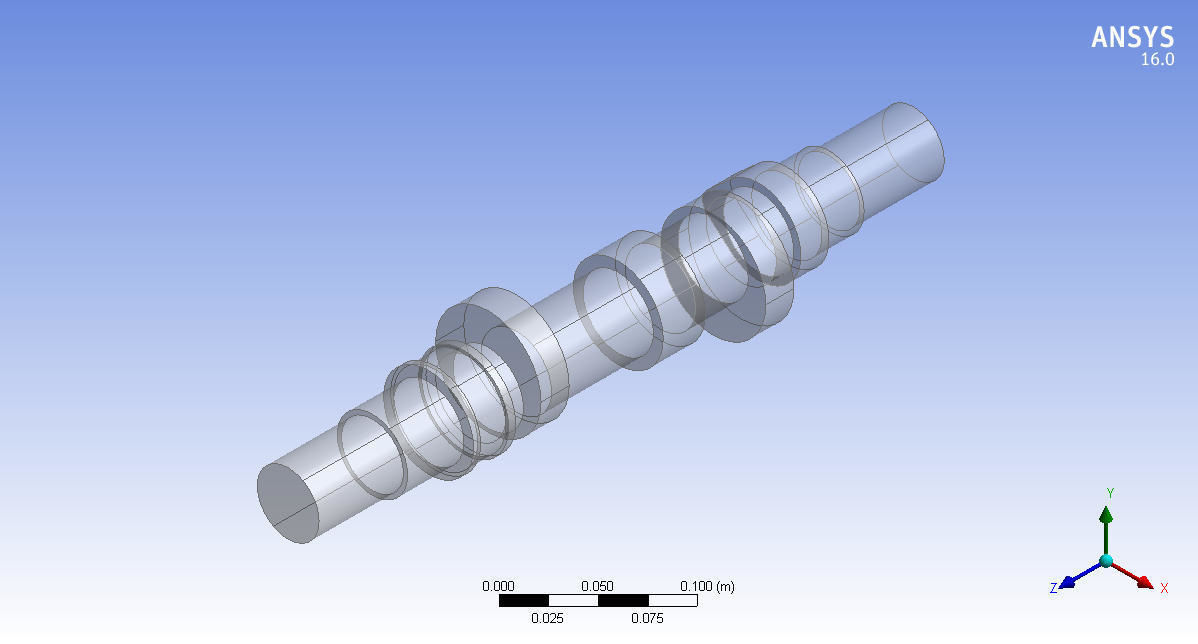
Camshaft 3d model design in Mechanical Engineering 3D print model
camshaft involves several key terms and components that describe its design and function. Here are the main elements:
Cam Lobes: The raised portions on the camshaft that push against followers to open and close engine valves.
Base Circle: The smallest diameter of the cam lobe, which serves as the reference point for measuring the lift.
Lift: The maximum height the cam lobe reaches from the base circle to the peak of the lobe, determining how far the valve opens.
Duration: The period during which the valve remains open, typically measured in degrees of crankshaft rotation.
Lobe Center Angle (LCA): The angle between the centerlines of two adjacent cam lobes, influencing valve timing and overlap.
Ramp: The gradual incline or decline of the cam lobe that allows smooth movement of the follower.
Follower: The component that rides on the cam lobe, translating its motion into valve movement.
Camshaft Gear: Connects the camshaft to the crankshaft, ensuring synchronization of valve timing with the engine cycle.
Timing Belt/Chain: A belt or chain that drives the camshaft from the crankshaft, maintaining proper timing between the two.
Material: Camshafts are often made from steel or cast iron for durability and strength.


