Before I talk about this project I have to say thanks to Andrew at Wizo Script (http://www.wizotools.com/). His script program turn not only a very tedious drawing task but EXTREMELY error prone nightmare, into a very simply an easy task (as will be explain later). Your the man Andrew. Thank you.
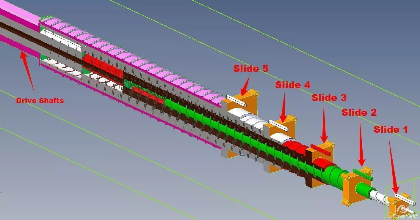
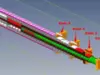
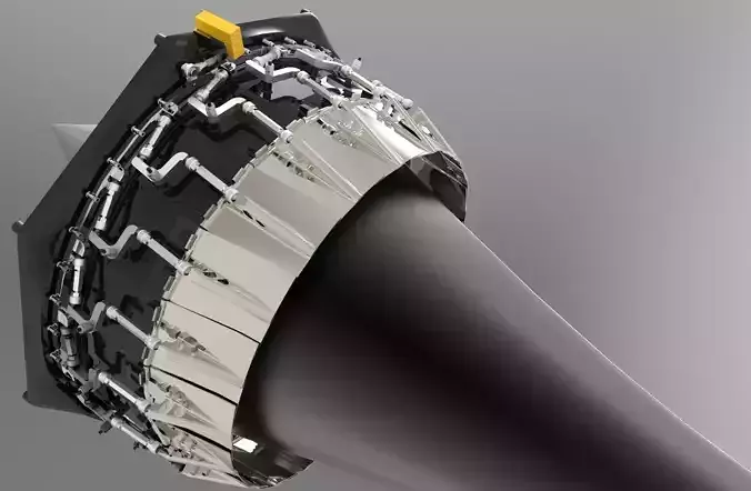
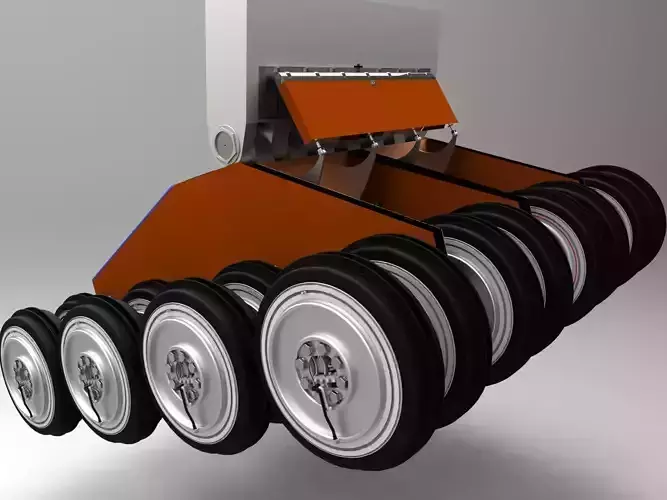
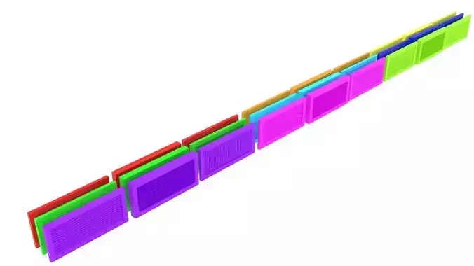
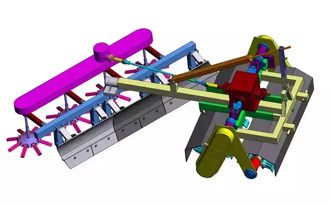
Now for the project:I need to extend and retract a 45 Meter wing. Not only I don't have room for a 45 Meter jack screw, the 60 support slides ( required for proper support ) meaning there has to have the same spacing over the entire wing. A single jack screw would not work with out some form of mechanical means that ensures that the supports are equally space. So the early version I tried to use a scissor jack actuator. I was always had concerned if it could proved the require torque and strength for the job. That’s when awaiting my morning coffee to brew I came up with a segmented jack screw (for lack of terms). Basicly it's a jack screw but broken into segments. By keeping the inner tube stationary and the outer tube rotates (please see the first 5 slides screen shot). As you can see as the outer tube rotates it retracts or extends it's segment according to the drive rotation. Meaning all slides spacing is equal no matter how far the wing is retracted or extended providing the proper support.
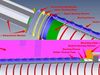
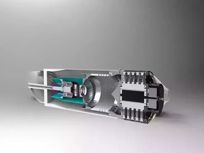
Looking at the exploded view screen shot, you will see there is 7 parts per segment. The 8th part is the base wing slide drawing, that the script draws a mounting seat well for each segment jack mounting plate. Also the screen shows how tedious and error prone these draws would if drawn by hand. The problem come in with the parts dimensions. Each part's dimensions has to be just right so the segments will assembly and operate properly. With number of parts per segment and there is 60 segments that means the would be 480 parts files. With configurations this cuts the number of files to just 8, one for each part. Not only configurations cut the number of files, it makes the drawings a piece of cake. I only to have to draw the 8 parts once (which I used the base configuration) . As I draw the parts I labeled the dimension that changed in each segment a name which the script updates according what segmented it's working on. What this all means I only to draw up the 8 base parts once, and let the script do the hard work. It took the script about 3 hours to run with out any errors.
The drive shaft driving gear is not shown here because it's work in progress. This gear train I'm going to use Wizo Script gear built in generator functions.
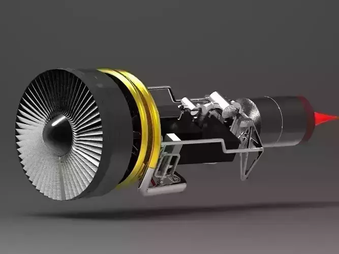
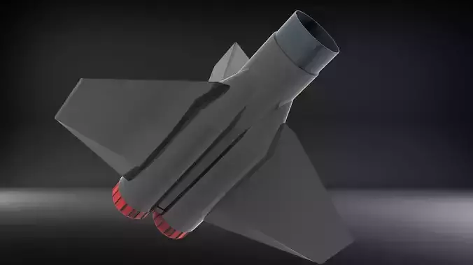
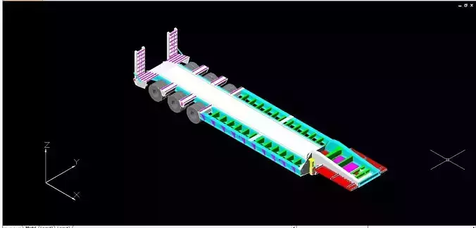
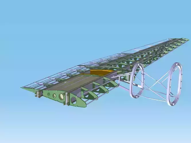
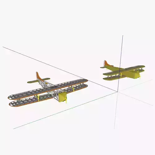
The last screen shot is of the wing as it sits right now. Please remember this a work in progress. It does NOT show all the internal supports. It's just a test drawing that does show how the segmented jack screw is use to extend or retract the win.Each wing panel is attach to the next panel's first slide:Wing Panel 1 . Slide 1&2 Attaches to Wing Panel 2 Slide 3Wing Panel 2 Slide 3 -> 11 Attaches to Wing Panel 3 Slide 12Wing Panel 3 Slide 12 -> 23 Attaches to Wing Panel 4 Slide 24Wing Panel 4 Slide 24 -> 38 Attaches to Wing Root Slide 39This explains why the slides need to equally space.
The ZIP file has the script in ODT and actual Wizo Script format,. A Geomagic Package the contants the base parts an base assembly. A video that shows the first 10 segments being drawn.