1/11
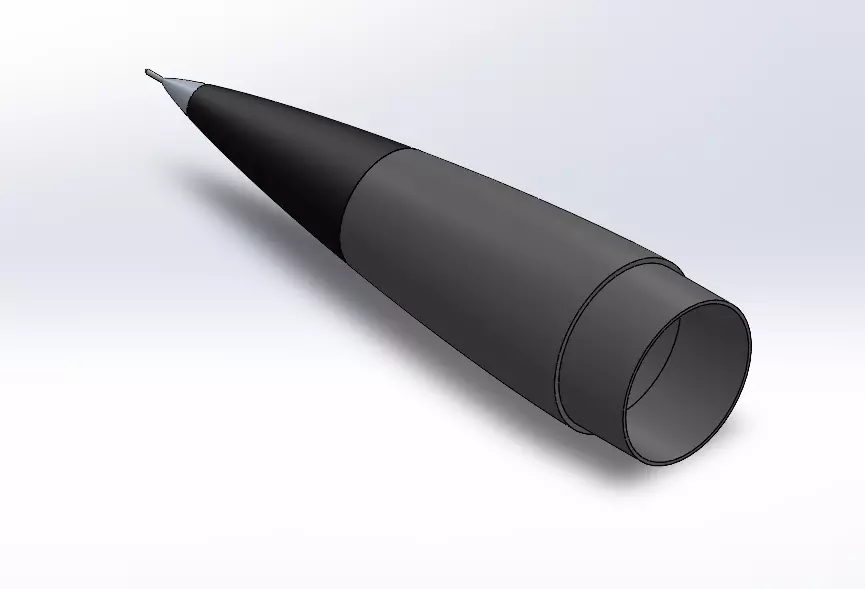
This is a precisely modeled LD-Haack (Von Kármán) style nosecone, based on the Haack series (C = 0) equations, designed to minimize aerodynamic drag for model rocketry applications.
The geometry was generated via MATLAB and modeled in SolidWorks for high-fidelity export and production. The shape ensures smooth airflow and optimal aerodynamic performance for subsonic and supersonic regimes.
Model Structure:
Aluminium Tip (ideal for machining or metal printing – optional)
Body Part 1
Body Part 2
These 3 parts form the full aerodynamic shell of the nosecone. Internal mounts (e.g., for Pitot or sensors) are not included, but the geometry allows room for custom integration.
Features:
Von Kármán profile (C = 0) for lowest drag per given length & diameter
Modular 3-part design for easier printing or machining
Printable in FDM,SLA,PLA,NYLON....
Can be adapted for Pitot tube installation if desired
Suggested Materials:
Tip: Aluminum (machined or metal-printed)
Body Parts: Nylon 6, PETG, or PLA+ (reinforced if needed)
Printing Guidelines:
Layer Height: 0.2 mm
Infill: 30–60%
Supports: Recommended for the tip interface
Tolerances: Designed for ±0.1 mm fit
Included Files:
aluminium_tip.stl
nosecone_part1.stl
nosecone_part2.stl
Note: The aluminium tip is included without a Pitot tube hole, allowing users to assemble a fully enclosed and aerodynamic nosecone without instrumentation.This makes the model suitable for use in non-sensor rocket configurations or as a general aerodynamic prototype.
Note: This model includes only the aerodynamic shell. Sensor mounts, Pitot adapters, or recovery features are not included, but can be custom added by the user if needed.Settings and manufacturing instructionsAssembly: 565.78 mm
The model consists of 3 main parts:
Aluminium Tip 49.57 mm
Body Part 1 229 mm
Body Part 2 324.21 mm
The parts are designed to fit together with friction or light sanding. Bonding using epoxy or cyanoacrylate (super glue) is recommended for permanent assembly.
The nosecone can be mounted onto a rocket body using your own adapter or coupler system (not included).
3D Printing Guidelines:
Recommended printing orientation: Vertical, tip facing up
Layer Height: 0.2 mm
Infill: 30–60% (depending on flight/stress expectations)
Wall/Perimeter Shells: 3–5
Supports: Required only at the bottom connection faces
Material Suggestions:
PLA+ (for prototypes)
PETG or ABS (for functional use)
Nylon 6 (for durability and heat resistance)
The aluminium tip can be metal 3D printed or machined for best results, especially in high-speed applications.
Tolerances:
Designed with a tolerance of ±0.1 mm for 3D printing compatibility
You may need to lightly sand or post-process mating surfaces for a tight fit
Customization:
The internal volume of the nosecone allows for user-defined modifications (e.g., sensor housing, recovery hardware)
Tip and internal walls can be drilled or adapted as needed
REVIEWS & COMMENTS
accuracy, and usability.


