
Full Printable ITX Case Mac Pro 2013 style 3D print model
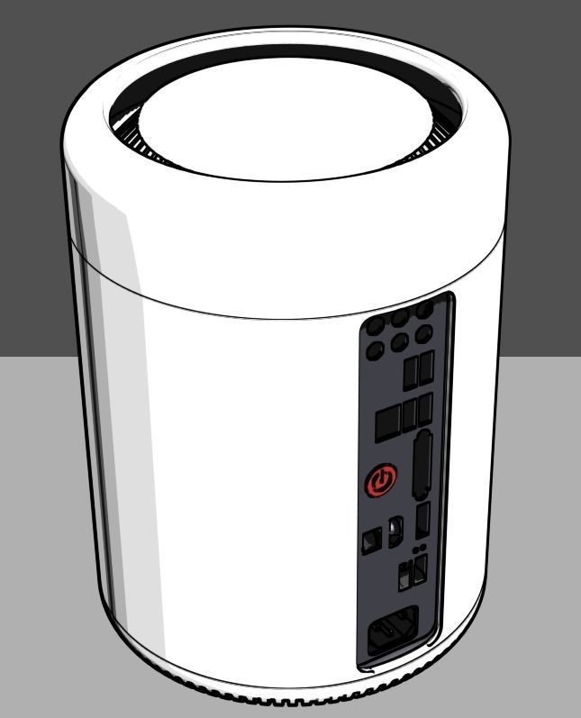
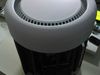
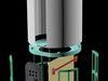
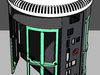
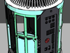
ITX format computer case fully printed on a 3D printer To build You need the skills of working with electricity and computer components The size and shape of parts adapted for printing on 3D printer with a maximum print area 200x200x200 mm Printing Material ABS and PLA print time of approximately 70 hours layer 0.22-0.24mm speed 60-70mm/s
PLA - need approximately 1kg for all case shells and grills, top and bottom mount base (top grill, bottom grill and top cap detail printed with support structures) ABS - about 150gramm for MB mount plate, HDD mounting frame and other detail assembly is made using the M3 screws and nuts, glue and double-sided tape
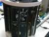
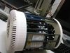
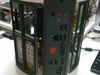
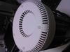
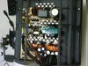
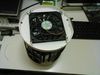
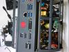
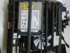
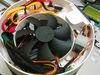
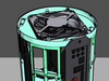
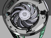
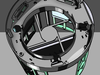
Motherboard mini-ITX MSI H97I AC + CPU Intel i5-4440 + LowProfile Cooler Power Supply CHEIFTEC GPS-450A8 - pulled out of the casing are shortened wires coming to the motherboard HDD 2.5" formfactor Intel 530 series SDD + Hitachi Travelstar 7K1000 Bottom fan from power supply, from this removed mount frame and fan mounted with cable ties Top fan low profile 120mm
- my costs paid off price reduced
- Super awesome! Just recently became an intern for a company and we just got a 10x10x10 inch 3D printer (getting set-up right now). Once that is finished, I'm going to get your design and try to build my own Hac Pro! What are the dimensions (exterior and interior) of the chassis? Again, awesome work!
- External dimensions of the assembled case: 270mm height and 198mm diameter Internal dimensions correspond to the specifications of the motherboard MINI ITX format If you use a different motherboard need to change the back cover template for this is contained in the files And of course I'll help you with advice for printing and assembly If you have no experience in 3D printing may not be able to print large parts
- hi mate, could a asus z97i-plus work with this case and what modifications would i need to make.
- Hi! You need to change the rear panel, and the power button. Files includes a template for the production of the rear panel. For myself, I did a paper template with holes. And then you can make the back cover with the correct holes.
- Could it work to just make a cut out for the alloy back cover that comes with the mother board? Keep the power plug there and then I can just drill out a hole and add in my own button? I'm not the best at design could you do this for me I can pay!
- Panel that comes with the motherboard is not very well suited Prints are now the main part of the body Build and install only the motherboard I'll send you the file to print a paper template so we can do everything exactly And I need to know which button will be used to power
- Ok then, jacob.bloy at gmail.com is probs a better way to communicate, or I can just use your button but move it, or http://www.jaycar.com.au/Electromechanical-Components/Switches/Pushbutton/IP67-Rated-Illuminated-Momentary-Switch-Green/p/SP0797
- Could it work to just make a cut out for the alloy back cover that comes with the mother board? Keep the power plug there and then I can just drill out a hole and add in my own button? I'm not the best at design could you do this for me I can pay!
- Very nice project :)
- Would there be room to mount a gpu in a potential build? Something like a Gigabyte GeForce GTX 970 Mini ITX?
- I have thought about such a modification. I'll do it as soon as I get some free time.
- Did you by chance find the time to make a gpu variant?
- I made the attempt. But the presence of the GPU violates the proportion. It looks just like a bucket. It's ugly. I will not give up this idea, but the design is completely different.
- First
- ⟨
- 1
- 2
- 3
- 4
- ⟩
- Last