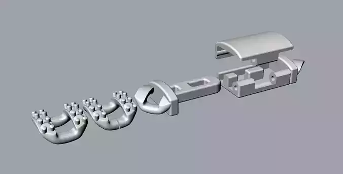
Low-Cost CNC Pen Plotter — Arduino UNO + GRBL + 3D Printed Frame
A fully 3D-printable, budget-friendly CNC pen plotter (drawing machine) built around parts you probably already have in a drawer: an Arduino UNO, a CNC Shield V3, three A4988 drivers, two NEMA-17 motors and a single 28BYJ-48 geared stepper for the pen lift. It writes text, produces clean technical drawings and even traces PCB artwork onto paper — all from a rigid, self-built Cartesian frame.
This design was developed as an engineering graduation project. The goal was simple but strict: build a reliable drawing machine using only cheap, widely available components, with no permanent hardware modifications. Everything here is printable, sourceable and reversible.
What it does?
Writes handwriting-style textDraws technical / vector drawingsTraces PCB copper artwork onto paper (great for toner-transfer prep)Runs on the open-source GRBL motion controller, so it's fully standard and hackable
System at a glance
PropertyValueKinematicsCartesian (X, Y, Z)Drawable work area251 mm × 222 mmPhysical travelX ≈ 253 mm · Y ≈ 224 mmXY driveNEMA-17 + GT2 belt on linear rodsZ (pen lift)28BYJ-48 geared stepper + pinion & rackControllerArduino UNO + CNC Shield V3Drivers3 × A4988 (1/16 microstepping)Power12 V supplyFirmwareGRBL (open source)
Mechanical design
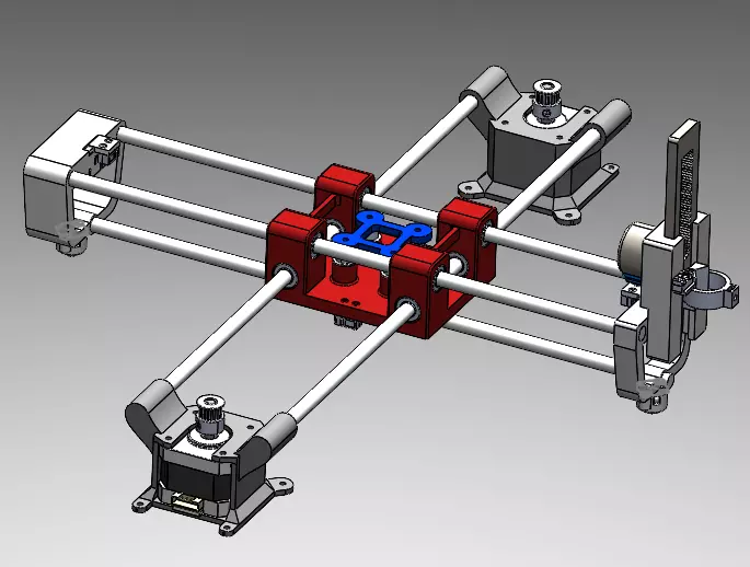
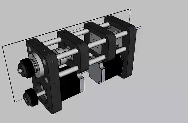
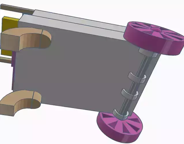
The machine is a classic Cartesian layout: the X and Y axes position the pen tip over a flat sheet, and a compact Z axis lowers and lifts the pen against the paper. The whole structure rides on 8 mm linear rods with LM8UU bearings, keeping the moving mass low and the motion smooth.
X and Y motion
Both X and Y use the standard, proven desktop-CNC recipe: a NEMA-17 stepper driving a GT2 6 mm timing belt over toothed and idler pulleys, with the carriage sliding on linear rods. A micro limit switch sits at the end of each axis for referencing. This gives crisp, repeatable positioning across the full ~253 × 224 mm envelope.
Z axis — the interesting part
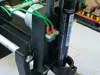
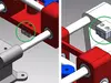
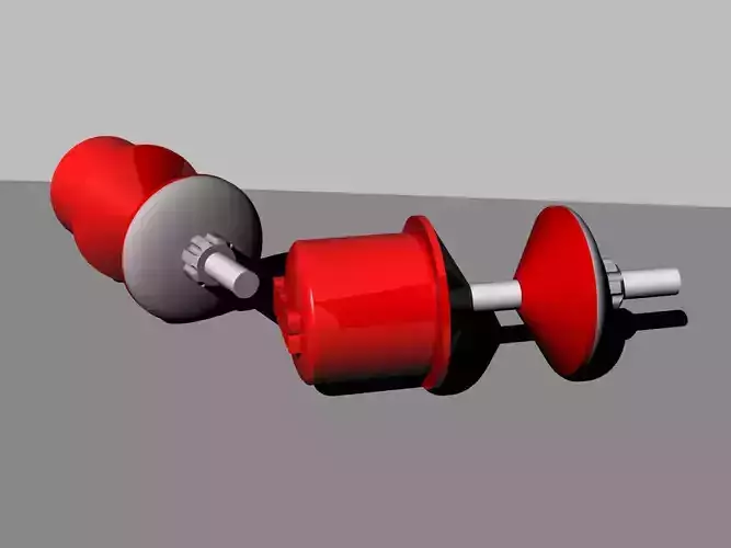
Instead of buying a third NEMA-17 just to lift a pen, the Z axis reuses a cheap, ubiquitous 28BYJ-48 geared stepper. Rotary motion is converted to linear pen travel through a pinion-and-rack mechanism:
Pinion: 22 teeth, 12 mm outer diameterRack: 64.25 mm long, 39 teethLinear travel per pinion revolution: ≈ 36.24 mmMaximum Z travel: ≈ 64.25 mm
Combined with 1/16 microstepping, this yields a very fine ≈ 904 steps/mm on Z — far more resolution than pen lifting needs, which keeps the pen-down/pen-up motion clean and quiet.
The pen uses a simple three-level scheme — pen-down (drawing on the paper surface), pen-up (a small ~2 mm hover for travel moves between strokes) and park (a safe resting height). These levels are referenced to the measured paper surface rather than a fixed offset, so the machine still works even if the pen is remounted at a slightly different height.
Limit switches
All three axes carry micro limit switches at their travel ends. Besides protecting the mechanism, they act as position references for the machine's start-up calibration, giving a repeatable origin without any expensive homing hardware.
Electronics & wiring
The electronics are deliberately kept to the most common, lowest-cost stack in the hobby CNC world.
Controller stack
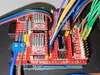
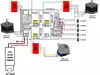
An Arduino UNO (ATmega328P) runs GRBL and plugs straight into a CNC Shield V3. The shield hosts the three stepper-driver sockets, the microstep jumpers, and the limit-switch and motor connectors — all pre-routed to match GRBL's pin map, so no extra wiring is needed between firmware and board.
A4988 driver configuration
Each axis is driven by an A4988 module:
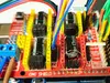
Microstepping: set to 1/16 via the MS1/MS2/MS3 jumpers under each driver. On the Z axis this smooths the 28BYJ-48's motion and reduces vibration.Current limit (Vref): trimmed with the on-board potentiometer to suit each motor.
The 28BYJ-48 bipolar trick
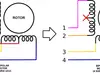
By default the 28BYJ-48 is a unipolar motor (5 wires) usually driven by a ULN2003 board — but the A4988 is a bipolar driver. The fix is elegant and fully reversible: isolate the motor's center-tap (red) wire so its two windings can be driven independently as a bipolar motor.
This step is mandatory. Without isolating the center tap, a 28BYJ-48 will not step correctly on an A4988. It's just a wire that gets disconnected — no soldering, no permanent modification.
Because this motor has a high coil resistance (≈ 420 Ω), its top speed and acceleration on Z are naturally limited. In practice, keeping Z feed ≤ ~200 mm/min and acceleration modest keeps every move reliable and step-loss-free. This is a physical property of the motor, so it's handled cleanly in the firmware parameters rather than fought against.
Pin map (GRBL / UNO / CNC Shield V3)
FunctionArduino pinNoteX STEP / DIRD2 / D5X axis step & directionY STEP / DIRD3 / D6Y axis step & directionZ STEP / DIRD4 / D7Z axis step & directionDriver ENABLED8Common to all A4988sX / Y limitD9 / D10Limit switch inputsZ limitD11See note belowSpindle EN / DIRD12 / D13Unused on a pen plotterReset / Hold / StartA0 / A1 / A2GRBL control inputs
Handy tip for CNC Shield V3 users: the shield physically wires the Z limit switch to D11. In stock GRBL, VARIABLE_SPINDLE reserves D11 for PWM and moves Z-limit to D12 — so the switch never reports. Disabling VARIABLE_SPINDLE returns Z-limit to D11 and makes the switch work again, with zero hardware changes. A pen plotter has no spindle, so nothing is lost.
Power & grounding
A single 12 V supply feeds the drivers through the shield; the Arduino is powered over USB or through the board. All grounds share a common reference. No extra power rails or modifications are required.
Bill of Materials
LM8UU linear bearing (8)8 × 350 mm aluminium rod (3)8 × 400 mm aluminium rod (2)3D printed parts (10)GT2 6 mm smooth idler pulley (5)GT2 6 mm 20-tooth pulley (2)GT2 6 mm timing belt (1 m)Ball caster wheel (2)NEMA-17 stepper (2)28BYJ-48 stepper (12 V) (1)M3×20 screws (5)M3×10 screws (10)M2×10 screws (8)M3×10 wood screw (8)M2 (8)/M3(2) nutMicro limit switch (5)22 AWG wire (1 m)Arduino UNO (1)CNC Shield V3 (1)A4988 driver (3)12 V power supply (1)2.54 mm 2-pin jumper (9)
Printing the parts
10 printed parts make up the frame brackets, carriages, motor mounts, pen holder and Z pinion housing.Recommended material: PETG for stiffness, temperature stability and durability of the moving parts.Printed on: Bambu Lab A1.Suggested settings: 3–4 walls and 20–40% infill for structural brackets; watch tolerances on the bearing seats and the pinion.
What you can make with it?
Handwriting & text — greeting cards, labels, signaturesTechnical / vector drawings — clean line art, diagrams, geometryPCB artwork — trace copper layouts onto paper as a base for prototyping
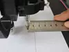
Dimensional accuracy is solid: a commanded 10 mm line measures 10 mm on paper, thanks to the correctly derived steps/mm values and keeping every axis under its step-loss limit.
Notes
This is an open, budget-oriented build meant to show that a dependable vector-drawing machine can be made from the cheapest common parts through good mechanical and electronics choices. Motion is handled by the open-source GRBL firmware. Feedback, remixes and build photos are very welcome — happy making!