High-quality 3D assets at affordable prices — trusted by designers, engineers, and creators worldwide. Made with care to be versatile, accessible, and ready for your pipeline.
Included File Formats
This model is provided in 14 widely supported formats, ensuring maximum compatibility:
• - FBX (.fbx) – Standard format for most 3D software and pipelines
• - OBJ + MTL (.obj, .mtl) – Wavefront format, widely used and compatible
• - STL (.stl) – Exported mesh geometry; may be suitable for 3D printing with adjustments
• - STEP (.step, .stp) – CAD format using NURBS surfaces
• - IGES (.iges, .igs) – Common format for CAD/CAM and engineering workflows (NURBS)
• - SAT (.sat) – ACIS solid model format (NURBS)
• - DAE (.dae) – Collada format for 3D applications and animations
• - glTF (.glb) – Modern, lightweight format for web, AR, and real-time engines
• - 3DS (.3ds) – Legacy format with broad software support
• - 3ds Max (.max) – Provided for 3ds Max users
• - Blender (.blend) – Provided for Blender users
• - SketchUp (.skp) – Compatible with all SketchUp versions
• - AutoCAD (.dwg) – Suitable for technical and architectural workflows
• - Rhino (.3dm) – Provided for Rhino users
Model Info
• - All files are checked and tested for integrity and correct content
• - Geometry uses real-world scale; model resolution varies depending on the product (high or low poly)
• • - Scene setup and mesh structure may vary depending on model complexity
• - Rendered using Luxion KeyShot
• - Affordable price with professional detailing
Buy with confidence. Quality and compatibility guaranteed.
If you have any questions about the file formats, feel free to send us a message — we're happy to assist you!
Sincerely,
SURF3D
Trusted source for professional and affordable 3D models.
More Information About 3D Model :
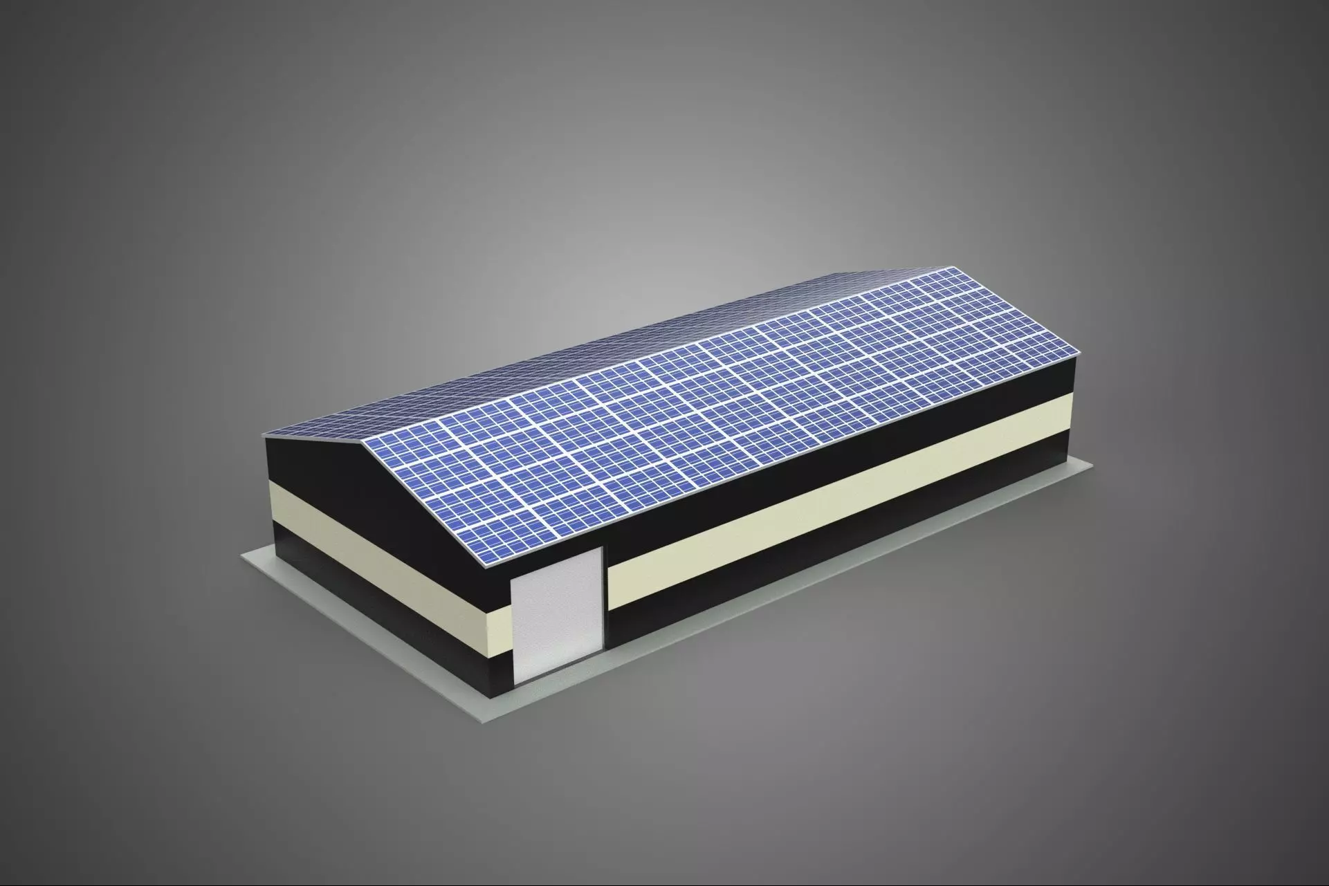
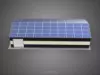
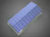
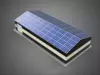
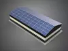
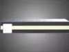
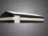
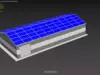
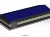
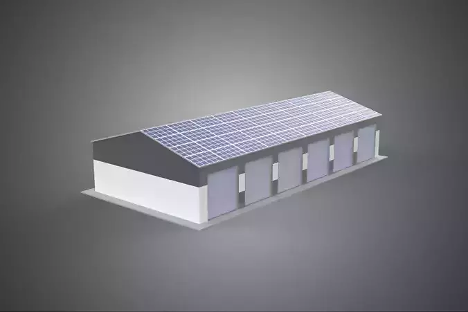
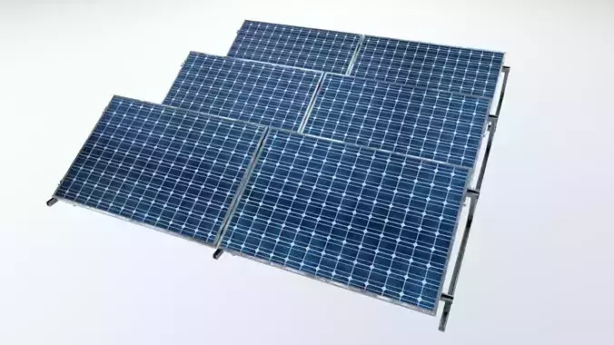
The subject, titled ROOFTOP ARRAY ECO SOLAR PANELS STRIPED UTILITY BUILDING FACILITY, refers to a specialized infrastructural installation combining renewable energy generation with a functional industrial structure. This description details the principal components, operational context, architectural features, and ecological implications of such a composite facility.
Facility Overview and Context
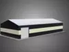
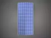
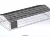
The structure serves primarily as a utility building, likely housing essential mechanical, electrical, or telecommunications infrastructure (e.g., pumping stations, data centers, storage depots, or power distribution switchgear). Its designation as a striped utility building typically denotes a non-standard aesthetic treatment, often involving high-contrast horizontal banding utilized for visibility, safety coding, or architectural distinction within an industrial park or remote location.
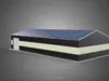
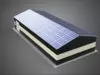
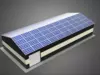
The critical defining feature is the integration of a substantial Rooftop Array composed of Eco Solar Panels. This configuration signifies a commitment to on-site decentralized energy production, offsetting the facility’s internal power consumption (net metering) or feeding surplus energy back into the local grid infrastructure.
Renewable Energy System (Rooftop Array Eco Solar Panels)
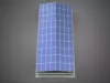
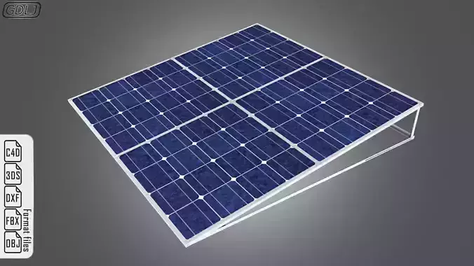
The solar photovoltaic (PV) system is mounted directly onto the building's roof structure.
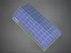
Panel Specifications: The use of Eco Solar Panels suggests a focus on sustainable manufacturing processes or materials, potentially incorporating recycled content, lower carbon footprint production methods, or enhanced efficiency technologies (e.g., PERC, heterojunction, or thin-film technologies designed for lower environmental impact). The array likely consists of crystalline silicon modules, the industry standard for durability and efficiency.
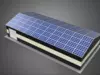
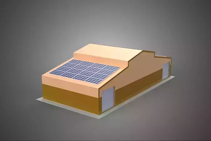
Array Configuration: The array is generally installed in a flush-mounted or low-tilt configuration, optimized to maximize power output based on the facility’s geographical latitude and the roof's structural capacity. Key considerations include:
-
Structural Loading: Ensuring the roof can safely support the distributed load of the panels, mounting hardware, and potential environmental loads (wind uplift, snow).
-
Inverter System: The PV array is connected to string or micro-inverters, responsible for converting the direct current (DC) generated by the panels into usable alternating current (AC). These are usually located near the array or within a dedicated compartment of the utility building.
-
Connectivity: The output is routed through disconnects, circuit protection devices, and integrated into the facility's main electrical service panel or a dedicated substation connection for grid export.
Ecological and Economic Rationale: The rooftop installation provides several environmental benefits, including the reduction of reliance on fossil fuels, mitigation of greenhouse gas emissions, and decreased energy transmission losses. Economically, the system lowers operational expenditures (OPEX) and provides hedging against fluctuating energy prices.
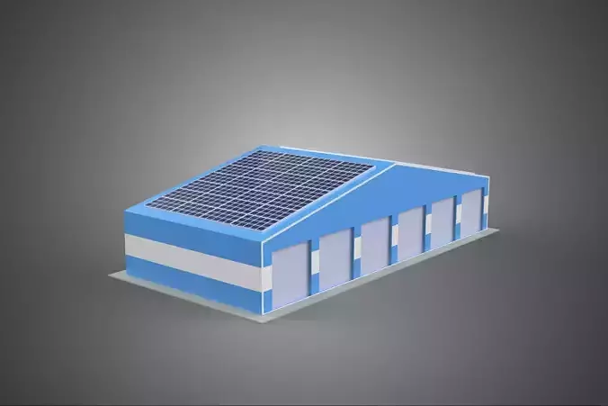
### Architectural and Utility Building Features (Striped Facility)
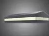
Building Type: The facility is a dedicated non-residential structure, characterized by robust construction materials (e.g., concrete block, pre-engineered metal, or structural steel) necessary to protect the internal utility equipment.
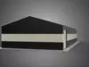
Exterior Treatment (Striped): The term striped refers to the facade's visual design. This often takes the form of alternating bands of color (e.g., safety yellow and black, or corporate colors), applied via industrial paint, cladding panels, or integrated masonry. In industrial environments, such striping can serve as a regulatory safety marker, highlighting the presence of restricted or high-voltage areas, or simply enhancing corporate identity.
Roof Structure: The roof must be sufficiently durable and watertight to withstand the penetration points and static load of the solar array. Flat or low-slope membrane roofing (TPO, EPDM) is common, facilitating easier installation and maintenance of the PV system.
Internal Functionality: The utility building houses essential functions required for grid stability or industrial processes. Examples include: battery storage systems complementing the solar array, HVAC units for cooling sensitive electronics, and proprietary control systems for the hosted utility infrastructure.
### Maintenance and Operational Parameters
Maintenance for this integrated facility involves two distinct regimes: routine structural and utility maintenance for the building envelope and internal equipment, and specialized maintenance for the PV array (e.g., panel cleaning, inverter diagnostics, wiring integrity checks). Operational efficiency metrics include the system's Performance Ratio (PR) and the utility building's energy self-sufficiency percentage.
KEYWORDS: Photovoltaic System, Rooftop Array, Utility Building, Renewable Energy, Solar Panels, Decentralized Generation, Sustainability, Striped Architecture, Industrial Facility, Energy Efficiency, Grid Tie, PERC Technology, Net Metering, Structural Load, Facility Infrastructure, Industrial Aesthetics, Energy Storage Integration, OPEX Reduction, Photovoltaic Modules, Flush Mount, Array Diagnostics, Low-Carbon Footprint, Electrical Switchgear, Building Envelope, Commercial Solar, DC-to-AC Conversion, Distributed Energy Resources, Installation Engineering, High-Contrast Facade, Infrastructure Resilience.