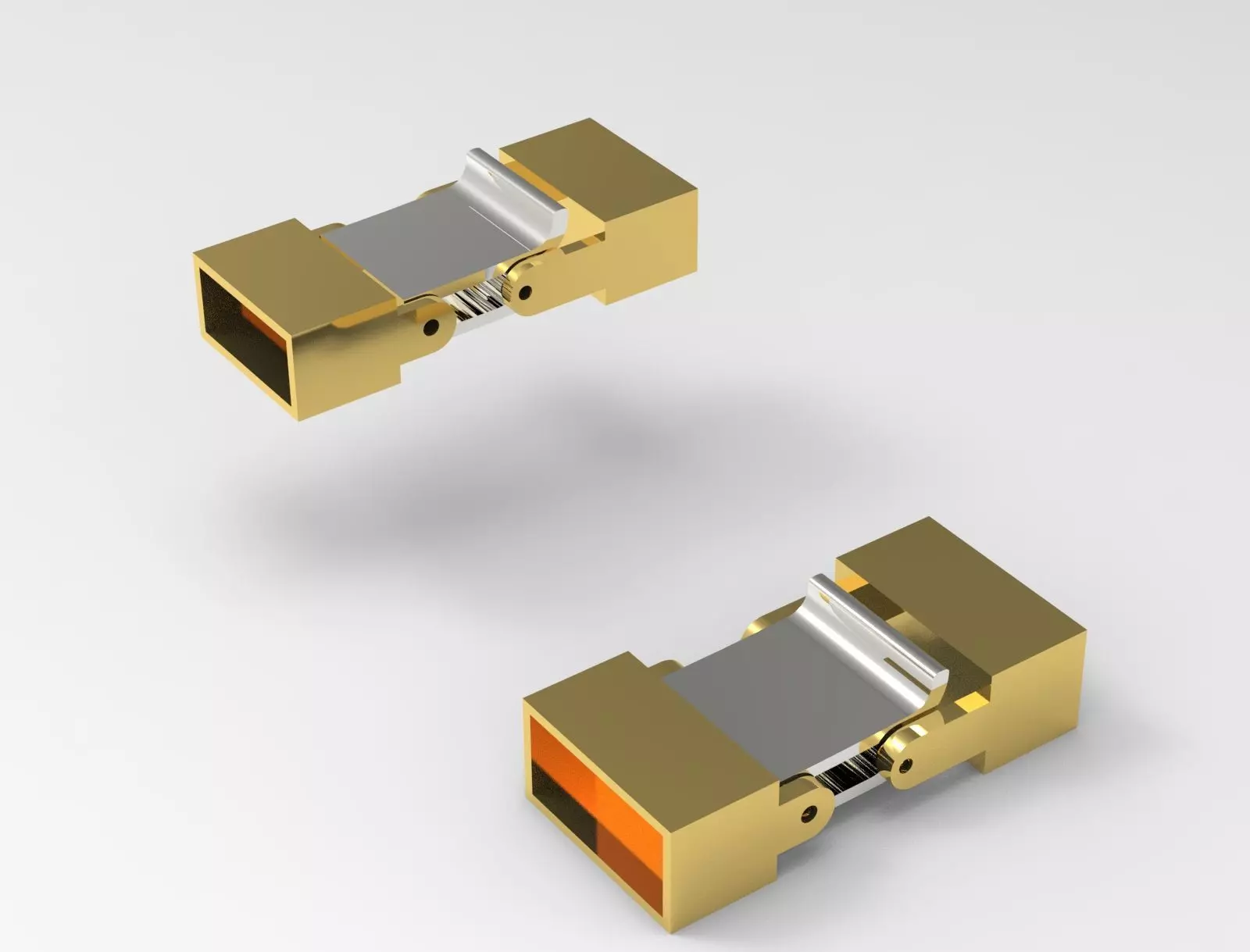
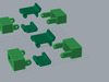
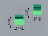
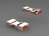
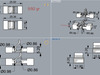
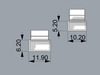
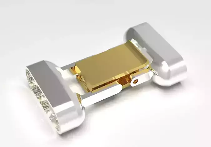
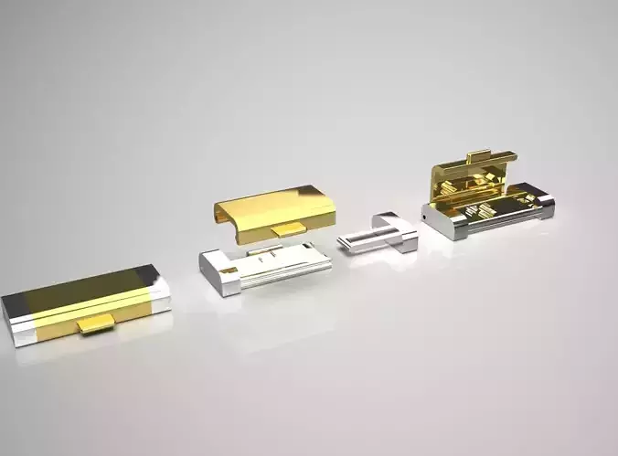
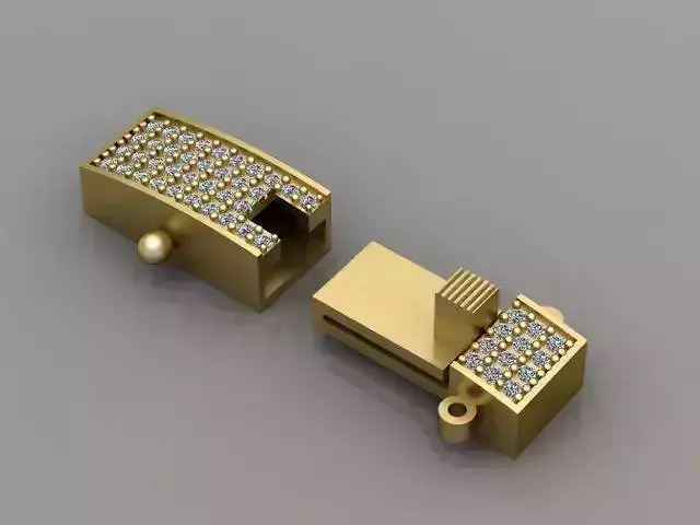
The image presents a detailed 3D model of a mechanical component, likely a part designed for assembly or mechanical functionality. It includes several views that aid in understanding its dimensions and features:
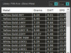
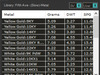
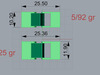
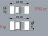
Looking Down View: This top-down view shows the overall layout and dimensions, highlighting the length and width of the component. It also includes weight annotations (e.g., 5/92 gr) that indicate mass specifications.
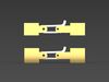
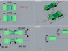
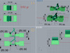
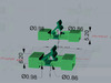
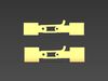
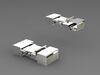
Through Finger View: This perspective displays the interior or hidden mechanisms of the component, offering a view of how parts fit together and suggesting where functional connections may occur.
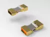
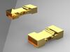
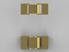
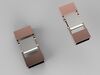
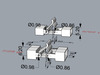
Perspective View: This three-dimensional view provides a clearer understanding of the shape and depth of the component, allowing for an assessment of its design from multiple angles.
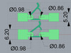
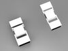
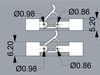
Side View: Displays the side profile and dimensions, revealing details about thickness and the arrangement of features.
The indicated measurements (in millimeters) and details about holes (e.g., diameter of 0.98 and 0.86) suggest it is intended for precise mechanical applications, likely requiring careful fabrication and assembly. The green color typically denotes a modeling phase in CAD software.
#3Dmodel #CADdesign #engineering #mechanicaldesign #productdevelopment #prototyping #designengineering #3Dprinting #modeling #mechanicalparts #industrialdesign #techinnovation #designconcept #fabrication #precisionengineering #designlife #customparts #digitalfabrication #solidworks #autodesk #fusion360 #simulation #engineeringdesign #makerspace #digitaldesign #partdesign #innovation #mechanicalengineering #3Dprintingtechnology #visualization #conceptdesign #technicaldrawing #3Dvisualization #tolerance #designinspiration #productdesign #creativeengineering #designthinking #prototype #mechanicalassembly #assemblydesign #engineeringart #objectdesign #manufacturingprocess #mechanism #designfeatures #designspecs #functionaldesign #hiresmodel #scale